Over the years as microcontrollers have become fast enough to do the heavy lifting, we have become used to 10 megabit Ethernet being bit-banged from interfaces it was never meant to emerge from. We think however that we’ve never seen one driven from an SPI interface, so this one from [Ivan] may be a first. With a cleverly designed transceiver using logic chips, it even offers a chance to understand something about the timing of an Ethernet interface, too.
The differential logic signals derived from a simple Ethernet transceiver can be read by an SPI bus, but for the lack of a clock line. The challenge was then to construct a circuit the would construct the required clock pulses from the state changes on the data line. This would become a monostable with XOR gate, and a shift register to handle the clock during the preamble phase.
The resulting circuitry fits neatly on a shield for the ST Nucleo 64 board, where while it might not be the obvious choice for an Ethernet shield it certainly does the job.
The least pleasant space in most houses is likely to be the space below it. Basements tend to be dank, dusty, and full of too many things that have too many legs. And even worse than the full basement is the dreaded crawlspace, which adds claustrophobia to the long list of unpleasantries that lie below. Sadly, though, a crawlspace might be a handy place to run wires, and if you’re hesitant to delve too deeply, this FPV cable-laying rig might be something to keep in mind.
This one comes to us from [Old Alaska] with very little detail other than what’s in the brief video below. The setup is clear enough — a need to run an Ethernet cable from one side of the house to the other, and a crawlspace to do it in. Also in the toolkit was an RC rock crawler with a field-expedient FPV camera. With Breaking Bad-style access to the crawlspace through a few floorboards, [Old Alaska] was able to deploy the crawler dragging a Cat 5 cable behind it. The terrain under the house made the rock crawler a good choice, with four-wheel-drive, locking differentials, and an articulating frame. The bot’s-eye view also makes it clear that actually crawling in this rubble-strewn crawlspace would be a painful affair.
With very little drama, [Old Alaska] was able to navigate the crawler across the crawlspace to the outer wall of the house, where he could fish the wire out and complete the connection — no fuss, no muss, no bloody knees. The only quibble we’d have is not running an extra length of pull rope with the wire. You never know when it’ll come in handy.
The standard Raspberry Pi computers have been in short supply for a while now, so much so that people are going to great lengths to find replacements. Whether it’s migrating to alternative single-board computers or finding clones of the Pi that are “close enough”, there are solutions out there. This method of building a full-size Raspberry Pi with all of the bells and whistles using the much-less-in-demand Pi Zero also stands out as a clever solution.
[SpookyGhost] didn’t build this one himself, but he did stumble across it and write a pretty extensive how-to and performance evaluation for the board, which can be found here. The adapter connects to the Zero’s HDMI and USB ports, and provides all the connectors you’d expect from a larger Pi such as the 3B. It’s not a perfect drop-in replacement though — you don’t get the 3.5 mm audio jack, and the micro SD card location doesn’t match up with where it should be on a “real” Pi.
All things considered, this is one of those solutions that seems obvious in retrospect but we still appreciate its elegance. It might disappear as soon as chip shortages stop being an issue, but for now we’ll take any solutions we can. If you don’t already have a Pi Zero on hand, we’ve seen some other successes replacing them with thin clients or even old smartphones.
Although it probably feels like forever to many of us since Category 5 Ethernet cabling became prevalent, now that 2.5 and even 5 Gbit Ethernet has trickled into the mainstream, a pertinent question that many probably end up asking, is when you should replace Cat-5e wiring with Cat-6, or even Cat-7. Since most of us are likely to use copper network wiring for the foreseeable future in our domiciles and offices, it is a good question that deserves a good answer. Although swapping a Cat-5e patch cable with a Cat-7 one between a network port and computer is easy enough, replacing all the network cable already pulled through the conduits of a ‘future-proofed’ home is not.
The good news is probably that Category 8 Class II (Cat-8.2) is all you need to run your 40 Gbit Ethernet network with standard twisted pair wiring. The bad news is that you’re limited to runs of only thirty meters before signal degradation begins to kick in. If you take things down a notch to Cat-6A or Cat-7 (ISO/IEC 11801 Class EA and F, respectively), you can do 100 meter runs at 10 Gbit/s just like 100 meters runs at 1 Gbit/s were possible with Cat-5e before. Yet what differentiates these categories exactly?
Spectral Bandwidth
The increased spectral use of the copper wiring by subsequent Ethernet standards.
The primary measurement that underlies these differences is called the spectral bandwidth, and is defined in Hertz. The bandwidth for twisted pair Ethernet wiring is in the MHz range, with Cat-5(e) hitting 100 MHz, Cat-6 250 MHz and Cat-6A 500 MHz. What this effectively means is the number of times that the signal can change per second before the receiver no longer is capable of receiving the entire session, at which point data loss will occur.
Much of the improvement in speeds over the same copper wiring is due to improved encoding schemes (also known as the line code), which are also responsible for boosting dial-up internet from a few baud to a few kilobytes per second. Here an essential factor is also the overhead of the encoding scheme, such as the old-school Manchester encoding used with 10BASE-T Ethernet. For its rated 10 Mbit you need at least 10 MHz spectral bandwidth to keep up, which worked fine even on Category 3 unshielded twisted pair (UTP) wiring, as is still commonly used for telephone wiring.
Eye pattern of a 100BASE-TX Ethernet data stream. MLT-3 can only transition one level at a time, unlike PAM-3. (Credit: Andrew A. Zonenberg)
Here the encoded signal uses 2-level encoding (binary 0 or 1), but it’s also possible to use more levels for the encoded signal, such as the 4-bit-5-bit (4B5B) encoding of 100BASE-TX (Fast Ethernet), which encodes 4 bits of data in 5 bits, which would normally require 125 MHz of bandwidth to transfer, but the final encoding step of 100BASE-TX is MLT-3 (Multi-Level Transmit), which as the name suggests cycles between three voltage levels (+1, 0, -1 V). Due to the use of MLT-3, to reach the effective data rate of 100 Mbit/s only a bandwidth of 31.25 MHz is required rather than 125 MHz.
Interestingly, 100BASE-T1 uses a three-level PAM-3 (Pulse-Amplitude Modulation) encoding, which makes it more practical for automotive and other embedded applications, but limits this version to a mere 15 meters on the same Cat-5e. For Gigabit Ethernet (1000BASE) the 1000BASE-T1 variant is similar in that it uses PAM-3 for the encoding, but requires (500 MHz capable) Cat-6A cabling due to its 375 MHz bandwidth requirements.
The more pedestrian 1000BASE-T uses 4-dimensional Trellis Coded Modulation (TCM 4D) and PAM-5 on all 4 wiring pairs in Cat-5, demanding a mere 62.5 MHz from the 100 MHz that Cat-5 is required to handle. Although a 1000BASE-TX standard was proposed in 2001 to replace the 1999 1000BASE-T standard that would use only PAM-5 on Cat-6 wiring, this was a failure in the market as the 1999 standard more than met the market’s demand.
Yet now that 2.5 Gbit Ethernet and beyond seem to have truly arrived, it ought to be clear that Cat-5 and the tweaked Cat-5e standards are now rapidly gaining legacy status, and should not be considered for new purchases and installations. Even though 2.5GBASE-T (using 64B66B, PAM-16 and DSQ128) can technically use 100 MHz Cat-5e wiring courtesy of its 100 MHz bandwidth requirement, this assumes flawless wiring. Putting in 500 MHz-capable Cat-6A would give much more leeway (up to 400 MHz-requiring 10GBASE-T), with a healthy tolerance in the case of degraded cables.
Twists And Turns
Cross sections of three different types of 10 gigabit network cables. (Credit: Tosaka, Wikipedia Commons)
With the basics of spectral bandwidth out of the way, a pertinent question that may have floated to the surface of one’s mind by this point is where the twists in ‘Ethernet cables’ (twisted pair cabling) are relevant. Perhaps more specifically: where does the extra spectral bandwidth in those different categories of networking cables come from?
The basic answer is that it is affected by the used conductor material (e.g. copper) and the amount of interference (EMI and crosstalk) which limit the effective range and bandwidth of the signal. For Category 6 and up this means that only copper (not e.g. copper-clad aluminium (CCA) ) is an acceptable conductor, leaving the remainder of the research focus on reducing the impact of external interference. The first line of defense here is found in the presence of the signal pairs, each of which form a balanced signal pair that enables significant amounts of noise to be rejected.
By also twisting these two conductors within a balanced pair around each other, the amount of electromagnetic noise they’re exposed to is reduced, while also reducing the amount of noise these twisted pairs expose nearby pairs to, effectively limiting the amount of crosstalk. The more twists per length of cable, the more significant this effect is. The relevant standards do not specify a specific number of twists (pitch) per length of cable, just that the cable can perform at the parameters required by the targeted standard.
In order to further increase noise rejection, the cable can be further shielded in a variety of ways, either with foil around the individual pairs (U/FTP), around all the pairs (F/UTP), or both (F/FTP). A network cable can be marked and sold as Category 6A if it passes a 500 MHz bandwidth and crosstalk test, for the latter measuring crucial parameters such as Near End crosstalk (NEXT, near the transmitter) and Far End crosstalk (FEXT, near the receiver). With Category 6+ wiring alien crosstalk (AXT) from neighboring cables becomes more crucial as well.
Squeezing Copper
Category 7, 7A and 8 cables use even stricter noise shielding than Cat-6A in order to bump the spectral bandwidth up to 600 MHz for Cat-7, 1 GHz for Cat-7A and a pretty amazing 2 GHz for Cat-8. As noted earlier, Cat-8 is what’s required to run networks at 25GBASE-T and 40GBASE-T speeds, albeit over fairly short distances (~30 meters). In general use you will find Cat-6(A), as well as Cat-7(A), with the latter being mostly advertised for fixed installation (using the solid core version), though you could argue that between a theoretical 500 and 600 MHz it’s somewhat of a toss-up, especially when taking into account factors like the quality of installation, such as the untwisting of pairs when punching them into a terminal block.
With either Cat-6A or Cat-7(A) run through the conduits of the new office or one’s dream house, it would seem likely that this is as far as copper will be pushed for now. As anyone who has recently browsed at their local IT networking store for 5 and 10 GBit cards and switches can probably attest to, at these extreme points of twisted pair networking the cost picture between a copper- and fiber-based network begin to somewhat blur together.
For equipment that supports SFP modules, it’s even possible to switch its interfaces between copper-based twisted pair and fiber-optic versions, which at least saves the trouble of replacing the entire device if upgrading the network to fiber. It’s quite possible that by the time that 10GBASE-T begins to feel as old and grizzled as 1000BASE-T today, fiber-optics may be the new mainstream standard. This would have the advantage of fiber-optics being immune to factors like EMI and crosstalk, while providing the potential for 100+ GBit home networks.
Until that time, it’s best to ensure you get your twisted pair cables from reputable brands, as anyone can put some lettering on a cable, yet not many have the test equipment lying around to validate that a ‘Cat-6A’ cable isn’t secretly a barely-Cat-5-cable with CCA conductors. Just so that you don’t wonder later why your ‘2.5 GBit network’ actually runs at closer to Fast Ethernet speeds.
Ethernet is ubiquitous, fast, and simple. You only need two diffpairs (four wires) to establish a 100Mbit link, the hardware is everywhere, you can do Ethernet over long distances easily, and tons of the microcontrollers and SoCs support it, too. Overall, it’s a technology you will be glad to know about, and there’s hundreds of scenarios where you could use it.
If you need to establish a high-bandwidth connection between two Linux boards in your project, or maybe a Linux board and a powerful MCU, maybe make a network between microcontrollers, Ethernet’s your friend. It also scales wonderfully – there’s so much tech around Ethernet, that finding cables, connectors or ICs tends to be dead easy. Plus, the world of Ethernet is huge beyond belief. Ethernet as most of us know it is actually just the consumer-facing versions of Ethernet, and there’s a quite a few fascinating industrial and automotive Ethernet standards thatflipmany of our Ethernet assumptions upside down.
Now, you might be missing out on some benefits of Ethernet, or perhaps misunderstanding how Ethernet works at all. What does it mean when a microcontroller datasheet says “has Ethernet interface”? If you see five pins on an SBC and the manufacturer refers to them as “Ethernet”, what do you even do with them? Why does the Raspberry Pi 4 SoC support Ethernet but still requires an extra chip, and what even is GMII?
Transmit The Basics
Ethernet is fundamentally about point to point connections – a single cable connecting two devices. If you have multiple devices you want to tie together into a network and Ethernet is what you’ve got available, you’ll want to use a switch, or a router with a builtin switch, or something else that has multiple Ethernet ports, then do individual point-to-point links between the switch and your devices, forming a star topology network. It used to be that you could use a coaxial cables for Ethernet and wire a single cable between computers, but those days are long gone, and the speeds were low enough that the major reason to miss those times is nostalgia.
There’s two versions of Ethernet you will encounter nowadays when it comes to speed – 100 Mbps (Mbit/s), often known as 10/100 because it usually also supports the old 10 Mbps mode, and 1 Gbps, known as Gigabit Ethernet. There’s also 2.5 Gbps, slowly becoming more commonplace in higher-end consumer tech like laptops, PCs and routers, but it’s yet to grace microcontrollers and SBCs, and I wouldn’t hold my breath – 100 Mbit/s is still enough for a ton of things. 5 Gbps and 10 Gbps are apparently on the horizon, but don’t expect to link up at that speed yet, unless you reuse some server card , invest some good money into it, or take time figuring out a cheap way. Of course, that’s bits per second, not bytes – if you want to calculate maximum file transmission speed where bytes/second is commonly used, you want to divide by 8, and subtract about 5% for packet overhead.
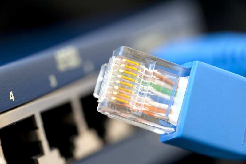
Physically, Ethernet tends to use cabling known as CAT5e, and connectors known as RJ45, with the proper name technically being 8P8C. Both the cables and the connectors are super commonly available, no end of life in sight. So, if you want to connect two boards together in a project of yours, maybe even with a shielded cable, using Ethernet cabling is a good bet – even if your project has no trace of Ethernet to be seen.
Speaking of cabling, Ethernet cables most certainly deserve their own part of the article. Let’s talk about cabling in as much detail as could be useful for an average hacker.
All The Wires
An Ethernet CAT5 cable has four twisted pairs inside of it, each one used for a separate differential pair – so, eight wires on total. Higher-speed versions of Ethernet like 2.5 Gbps will often wants higher-grade cabling than CAT5 – CAT6 or even CAT7, manufactured to a higher standard, but CAT5 (or CAT5E specifically) is what you’ll see the most of. Internally, some cables use multi-strand wires and some use solid core wires, and they work best in different scenarios. Short patch cables (known as “patchcords”) are better with stranded wiring, because it’s more flexible and easier to handle. However, stranded cables are less durable, and don’t work as well at longer distances. For more permanent and longer cabling, people tend to use solid core wiring, as it’s generally higher-quality, which helps on longer cable runs. Also, there’s different types of outer insulation – some are more fireproof, some are less toxic, and some are more resistant to environmental influence like UV light.
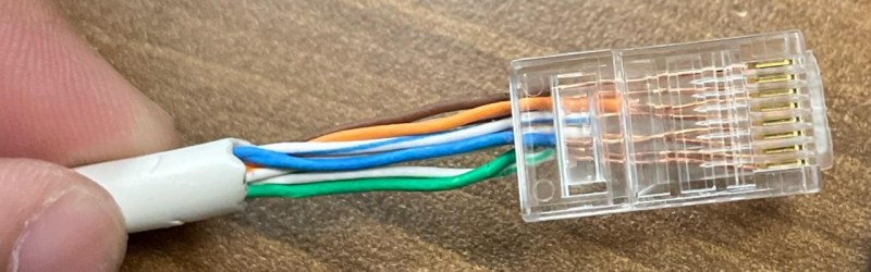
Out of the four pairs, 100 Mbps Ethernet only actually uses two of them, but 1 Gbps Ethernet uses all four. That’s why, on cheap old Ethernet hardware like low-end home routers with 100 Mbps ports, it’s not uncommon to see Ethernet sockets with only four pins out of eight – saving money by all means possible, after all, the two pairs in the cable would not be used anyway. There’s also hack potential in this, for instance, you can pull two 100 Mbps Ethernet links through a single CAT5 cable – that’s how my own Internet uplink used to work for a while about a decade ago, and that’s what the adapter pictured above does. And you can pull power through those pins in parallel with the Ethernet uplink, we’ll talk about that later, too!
Some Ethernet cables have internal shielding, but hardly anyone requires it – it’s used more in industrial or sensitive environments, and it might be required for higher-speed Ethernet standards too, but it’s rarely ever seen at home. So, most cables are not shielded, and they’re referred to as UTP (Unshielded Twisted Pair). There’s quite a few types of shielded Ethernet, which you might see referred to as FTP, SFTP, S/UTP or such – S- types (Shielded) wrap individual pairs or the cable in copper braid, FTP (Foiled) wraps them with foil, SFTP does both, there’s three-four different acronyms for each type of shielding combination, but don’t worry, you are not expected to remember this, just refer here or here if you ever need to know more. Also, don’t confuse it with SFP, that’s different! The type of shielding is typically written on the outer insulation along the length of the cable, too. If you are looking at a bundle of Ethernet cables of all kinds and you just want to find a shielded Ethernet cable for whatever reason, say, your robot’s internals, good shorthand is looking at the connector – it’s going to be metal-plated. Oh, and if you want the shield to be effective, at least one end has to actually be connecting that shield to something – many cheap devices don’t bother and use connectors fully made of plastic, with no plug shield connections in sight.
There’s only one standardized Ethernet connector, but there are a few different ways to cook it! In particular, you should know a few things about the standard pair-to-pin mappings, and how to actually terminate the cable in an Ethernet plug.
Plugs, Crimps And Mappings
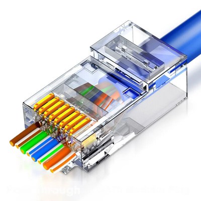
The usual Ethernet connectors are RJ45, technically correctly referred to as 8P8C. The plugs are easy to find in a wide variety of places, though with both CAT5e cabling and connectors, you don’t want to go for the cheapest options possible, especially given how much cabling claims to be a higher category than it actually is. With cheap plugs, they’ll be more likely to produce a faulty connection, or have the locking tab break away easily – fixable either through recrimping, strategic application of cable ties, or by using one of the ubiquitous plug sleeves.
The locking tabs are brittle enough, that all the fancy cables include some sort of tab protection
Most consumer-oriented Ethernet cables come with plug connectors put on them, but you can easily build your own Ethernet cables out of unterminated CAT5e lengths and plug connectors, as long as you can crimp the plugs onto the cable. There’s even Ethernet plugs that make the crimping process easier for beginners by letting you cut the wires after you insert them through, instead of painstakingly cutting them to exact same length before insertion! If you’re looking to learn how to crimp Ethernet cables, a YouTube tutorial is perhaps the best, and there’s no shortage of blog posts with pictures either – crimping is a craft extensively covered online. There’s one thing that you will inevitably need, and that’s a crimping tool.
A crimping tool is a handheld jig that compresses the plug pins in a way that makes the individual plug pin blades cut through the wire insulations and make electrical contact, which requires pressure applied very tactically and from a correct angle. You can also try and crimp a plug with household tools, but you’ll thank yourself for not doing that. Remember, having a proper crimping tool will save you both time and money, as well as a heap of frustration, because debugging Ethernet cables that make intermittent contact is not pleasant in the slightest. The most cheap crimping tools aren’t great to use and can lead to faulty crimp, so if you are about to do some crimping and got money to invest into proper tools, you will want to get a crimping tool that has great third-party reviews. Alternatively, see if your friendly neighbourhood hackerspace or networks engineer has a crimping tool you can borrow! If you need to test your crimping results, cable testers are cheap, and we’ve covered quite a few DIY ones.
Not a good crimp.
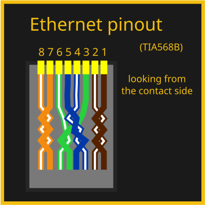
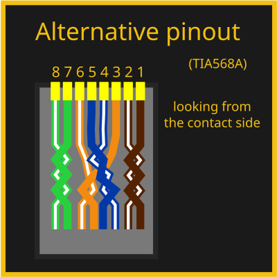
Of course, there are eight wires and eight pins, so you might be wondering – is there a mapping? The good news is – there is indeed! The bad news is – there are two of them. Fortunately, it’s easy to choose – the T568B mapping is the most commonly one used, with the T568A mapping being way less popular. Wikipedia tries to convince you that T568A is technically the best mapping ever, but you shouldn’t listen to it – a random cable in your cable box is way more likely to use T568B than T568A, and same goes for Ethernet cables worldwide.
You won’t need to learn the mapping, but if you want to, it will be all that easier as soon as you notice that the color and white wire pairs alternate. One quirk – the blue pair is in the connector center, which might feel counterintuitive. Here’s a fun fact, though – back in two-pair-utilizing 10/100Mbps days, this pair would sometimes be repurposed in offices, to carry a desk phone line alongside an Ethernet link to a worker’s desk within a single cable. You have to use the same mapping on both sides of the cable. However, in earlier days, there were cables where you had to use both mappings at different ends. Let’s take a small detour and learn about these cables, that you might just encounter if you work on really old tech.
Crossover
You might have heard of a thing called crossover cables. These were 10/100 MBps era Ethernet cables where the ends were crimped in two different ways, one in A variant and one in B variant – essentially, crossing RX and TX pairs. Direct (same pinout on both ends) mapping cables were used for switch-to-PC connections, and crossover cables could be used to connect two PCs or switches directly. Reason is, at the time, Ethernet expected you to cross RX and TX pairs ala UART, but ports on devices like switches would have them already crossed for convenience. Of course, this created a fair bit of problems at the time whenever you needed to rewire things.
However, for almost two decades now, crossover cables have been unnecessary, because every self-respecting Ethernet interface has adopted the technology called Auto-MDI-X – it lets you use both crossover and straight cables for connecting anything to anything, automatically detecting RX and TX and adjusting accordingly. You don’t need to bother with crossover cables nowadays, they have never been a thing for Gigabit Ethernet, and you’ll rarely ever find a piece of tech that doesn’t support Auto-MDI-X. If you want to learn more about crossover cables and tons of other Ethernet stuff, read here. It’s a still good thing to know exists in case you’re working with something seriously old that’s Ethernet-equipped, or if you stumble upon “crossover cable” as a term somewhere and wonder if you have a knowledge gap.
So Much More To Learn
We’ve covered pinouts, cabling and connectors, and that alone makes for a solid understanding of how Ethernet works at its core, at least as far as consumer tech is concerned. This is the surface-level of Ethernet, that you want to keep in mind as you hack on it further, and if you’ve had any knowledge gaps, hopefully this article has helped you cement your understanding. If you want to learn more in-depth, I’ve linked a couple articles inline – there’s never a shortage of Ethernet reading material online! Now, a lot of it is outdated or wrong, but thepagesI’velinkedhere, look pretty alright. Also, here on Hackaday, [Maya Posch] has written about Ethernet before in more depth – check herarticles out!
There are so many more sides to Ethernet, however – physical level insights, microcontroller and SBC requirements, MII and GMII, MACs and PHYs, magnetics and magjacks, mediaconverters, Power over Ethernet, switch ICs, embedded Ethernet, and a good few more hacker bits and pieces. Next week, with the base knowledge in hand, we shall dive further!
The 10BASE-T1 Ethernet standard is also known as ‘single pair Ethernet’ (SPE), as it’s most defining feature is the ability to work over a single pair of conductors. Being fairly new, it offers a lot of advantages where replacing existing wiring is difficult, or where the weight of the additional conductors is a concern, such as with the underwater sensor node project that [Michael Orenstein] and [Scott] dreamed up and implemented as part of a design challenge. With just a single twisted pair, this sensor node got access to a full-duplex 10 Mbit connection as well as up to 50 watts of power.
The SPE standards (100BASE-T1, 1000BASE-T1 and NGBASE-T1) 10BASE-T1 can do at least 15 meters (10BASE-T1S), but the 10BASE-T1L variant is rated for at least 1 kilometer. This makes it ideal for a sensor that’s placed well below the water’s surface, while requiring just the single twisted pair cable when adding Power over Data Lines (PoDL). Whereas Power-over-Ethernet (PoE) uses its own dedicated pairs, PoDL piggybacks on the same wires as the data, requiring it to be coupled and decoupled at each end.
Coupling and decoupling data with a PoDL powered device with 10BASE-T1. (Credit: Michael Orenstein & Scott, Electric UI)
Within the PoDL standard there are sixteen supported power classes along with a compatibility matrix for 10XXBASE-1T standards. Detecting of a PD-compatible device is done by the power supply providing a constant current source and the powered device sinking current to adjust the voltage to hit a specific level. With all of this knowledge and the requisite parts in mind and hand, a waterproof enclosure was sourced, firmware written and everything assembled to create a sensor node for temperature, humidity (SHTC3), motion (LSM6DSO) and depth/pressure (MS5837).
So that’s power and communications settled. All of a sudden, that homebrew ROV you’ve been dreaming of is starting to look a little more achievable.
Last time, we talked about the surface-level details of Ethernet. They are fundamental to know for Ethernet hacking, but they’re also easy to pick up from bits and pieces online, or just from wiring up a few computers in your home network. Now, there’s also a bunch of equipment and standards that you will want to use with Ethernet – easy to find whether used or new, and typically as easy to work with. Let’s give you a few beacons!
Routers And Switches
Whenever you see a box with a few Ethernet ports, it’s either referred to as a router, or a switch, sometimes people will even use the word “hub”! Fortunately, it’s simpler than it may seem. A router is a smart device, typically with an OS, that ties two or more networks together – routing packers from one network to another, and typically taking care of things like handing out local IP addresses via DHCP. A switch merely helps Ethernet devices exchange packets between each other on the same level – it’s typically nowhere near as smart as a router gets. Oftentimes, a home router will contain a switch inside, so that you can plug in multiple of your home devices at once. That’s the main difference – a switch merely transmits packets between Ethernet-connected devices, while a router is a small computer taking care of packet forwarding between networks and possibly including an Ethernet switch on the side.
A typical router’s internal structure
It’s easy to find a router for hacking purposes, and we’ve been reprogramming them for two decades now. Often, they run Linux, and if they don’t, they can be coerced. Inside a common router, you get a Linux device, typically with barely any CPU power, RAM or ROM, but you can run fun stuff alright – a file share, some control software for your robot, or maybe a tiny home automation suite.
Taking the other tack, it’s easy to build something that fulfills the functions of a router – take a low-power PC, put a Linux OS onto it, set up a DHCP server and packet forwarding script of some sort, and add a switch for anything you might want to network up. If you need a WiFi access point, you can plug in a network card and set up something like hostapd. Or don’t – there are also WiFi APs available: a single-purpose device with a single Ethernet port, that tend to be wonderful at what they do, unless you go for the cheapest option possible.
There’s plenty of hacking potential in Ethernet routers and switches alike. For routers, there’s the obvious OS hacking, but even that’s not all. For instance, you can use a multi-port router as a switch in a pinch, as long as you disable the “smart” features like DHCP server and don’t plug anything into the WAN port. Once, when I needed a gigabit Ethernet switch and only had a cheap router with gigabit ports, I did just that. Understand these devices, and you will be able to reuse them in a variety of ways. Speaking of reuse – if you have an outdated router, take one apart, and you can get RJ45 (8P8C) jacks, Ethernet transformers (aka magnetics), switch-mode PSU circuits you can reuse, and some nice WiFi antennas in case you need to boost your ESP32’s coverage in a pinch.
As for switches, here are a fewhacks that turn regular switches into “managed” switches that add extra quality of life features like VLANs, port mirroring, or security features. We’ve even covered a hack that lets you tap into the Linux OS powering a particularly fancy switch! Want to build your own Ethernet switch? We’ve previously shown you products from a company building hacker-orientedcommercialembeddable Ethernet switches, that I’m sure you could easily learn from and put your own spin on. The company involved started out as “open-source” but took down the hardware design file repo at some point after we started covering their products; thankfully, there are forks still available. Plus, switch schematics can be pretty easy to find, and teardowns even more so!
Have you heard about Ethernet hubs? “Hub” is generally a synonym for “switch” these days, but back in the 10 Mbps days, it used to be a different device – a passive way to tie three Ethernet devices into a network using resistors, diodes, or transistors. Every packet is sent to every device, of course, and it only works for low speeds because it makes the connection half-duplex, and the signal strength is weakened, but the upside is that it’s extremely simple. I’ve never encountered a hub in real life, but if you’re wondering, I’ve found two designs, one using resistors (translated, original) and another using diodes. Both of these designs have three ports – if you’re ever in need of a low-speed Ethernet network, this should do in a pinch.
Power over Ethernet
Speaking of things that you can build yourself, powering your devices is undoubtedly a priority. Let’s talk about Power over Ethernet, where you will find it, how you can build it on your own, and when you might want to reconsider doing that.
By [deavmi], CC BY-SA 4.0PoE (Power over Ethernet) is either one standard or multiple ones, depending on where you look. There’s the well-thought-out PoE standard, used in products of all sorts. It’s the one you are likely to know if you encounter PoE on a shelf, and it’s completely consumer-friendly and wonderful, and typically it will come with a heftier pricetag. Just like USB-PD, PoE does negotiation to check voltages and see if the consumer device is PoE-capable, and it also overlays the voltage on top of the signal – which means you can do Gigabit without worry.
There’s also the PoE “standard” where you use two pairs for 100 Mbps and then just put a high-ish DC voltage on two of the remaining pairs. It’s charitably referred to as “passive PoE”, and it is what you’re likely to encounter in cheap products. You’d better watch out to ensure that it doesn’t blow up your port – there’s no negotiation, and usual devices don’t take kindly to it. In addition to that, there are a few proprietary standards, like the Mikrotik Gigabit PoE.
The 802.3af PoE standard works by superimposing a DC voltage onto the signal, using two possible pair combinations, known as Mode A and Mode B respectively. There’s also a higher power option, which uses all four pairs for higher power devices. Power is only applied to the pairs after PoE negotiation, and negotiation only happens after a compatible device is detected on the other end. 802.3af PoE tends to come with a pricetag, and that’s mostly because it has a fair bit more electronics involved, typically even including a small but hefty transformer.
If your device doesn’t come with PoE and you want to add it the proper way, there’s also modules you can buy online and add inline, 802.3af injectors and extractors. It might take a fair minute to find one, but you generally won’t go wrong using a 802.3af-compliant PoE module if you want to go the DIY route while sticking to foolproof PoE tech – they make a lot of sense if most of your network already supports 802.3af and it’s just a few devices that don’t. Oh, and of course, it’s possible to design your own. If you do that, you can even add support for both proper 802.3af and passive PoE!
Passive PoE, the straightforward version, has its spot under the sun and in our toolboxes too. Of course, you better be careful shoving passive PoE-powered cables into places – it can burn out a port on your laptop or Pi, if you’re not careful. Nevertheless, if you’re fine with 10/100Mbps, have control over the network, and just want to wire up a Raspberry Pi or two, passive PoE is a wonderful way to do it – the cheapest, the simplest, and the most flexible. One classic hacky way to make passive PoE work is simply cutting into Ethernet cables, but if you’ll be touching the cabling often, remember that this is breakage-prone. If you want to make a passive PoE circuit easy to maintain when your network inevitably needs some tweaking, you can also buy passive PoE injectors and receivers online – and they’ll be much, much cheaper too! So, you exchange user error protection for lower cost and greater hackability – sounds like exactly the kind of tradeoff a hacker should know about.
Here’s my own advice for passive PoE, having wired up a couple of small-scale networks with it. You should clearly mark passive PoE cables, because they’re meant to go through a PoE tap (“injector”) before you plug them into any device – a red sharpie, maybe a piece of red tape, but a sticker that says “do not touch if you don’t know what you’re doing” is the best option problem. This is the most important part with passive PoE, and you might be able to guess why I stress it. You might be tempted to add PoE by soldering onto the pads of an Ethernet jack on your device’s PCB, but do a multimeter test first – it might be a jack with integrated Ethernet transformer, or there might be resistors connected to the unused pairs.
Also, you have to choose your voltage with passive PoE, and you can’t just do 5 V. The voltage drop over meters of Ethernet cabling is going to halve this voltage immediately, with barely anything left unless you’re powering something really low power. Remember, active PoE uses 48 V for a good reason – as you increase voltage, you decrease current needed to carry the same amount of power. 12 V might be tempting, but 24 V is significantly more advantageous, as long as you don’t use cheap DC-DC modules – those will fail you, especially when powering a Raspberry Pi. Last but not least, if you are about to re-crimp cable carrying a passive PoE link, remember to disconnect the other end, unless you want to have sparks fly.
We’ve covered PoE quiteabit, and even hacks that add PoE to ESP32 using 802.3af modules, reuse the Raspberry Pi PoE header for single-cable wireup, or even transmit Ethernet over DC power instead. Now, for a change, let’s talk about the polar opposite – a way to do Ethernet that does not allow you to do any power transmission at all, which is Ethernet over fiber optics, and how you can get there.
Media Converters
If you’ve ever hacked a bit further than pure home applications of Ethernet, you’ll know there’s a way to put it onto fiber optic. Fiber is wonderful for even longer distance runs than Ethernet can achieve, it’s even more resillient too. Sometimes it lets you reuse an existing fiber connection – many a provider now prefers pulling fiber. A piece of hardware capable of converting Ethernet to fiber is called a “media converter,” and they’re not that hard to find online as separate pieces of equipment – especially given that many are discarded by small-scale ISPs as they upgrade their tech.
A mediaconverter, functioning despite slightly suboptimal incoming fiber cable configuration
Now, unlike Ethernet, you can’t easily crimp fiber, you have to weld it with a special machine, and if you don’t have that machine, you might have to settle with buying pre-terminated fiber lengths. You also have to be seriously careful when bending fiber – it can’t withstand much abuse. However, if the upsides of fiber are tempting for you, what you can do is go find a media converter online, plug your Ethernet cable into it, and on the other port of it, or two ports, and bam, you get fiber Ethernet.
One unexpected use case for a hacker is total galvanic isolation – lightning-proofing your Ethernet links on the cheap. If you’ve ever wanted to add a surefire, guaranteed lightning protection to an Ethernet connection, converting it into a short run of fiber optic cable through two media converters is perhaps the best decision you can make! Fiber is also resilient to electromagnetically noisy environments.
At this point, you might be wondering – how exactly do you build new Ethernet devices? Whether it’s an ESP32, a DIY router, or an Ethernet-enabled stepper motor, worry not. Next time, we will go through the practical side of using Ethernet – Ethernet transformers, internals, and wireup, nuances like Bob Smith termination, magjack recommendations, PHYs and MACs, and how to bend the rules at the hardware level. For illustration and example circuit purposes, expect to see a fair few Ethernet-based hacks from all around the hacker world!
Internet connectivity in remote areas can be a challenge, but recently SpaceX’s Starlink has emerged as a viable solution for many spots on the globe — including the Ukrainian frontlines. Unfortunately, in 2021 Starlink released a new version of their hardware, cost-optimized to the point of losing some nice features such as the built-in Ethernet RJ45 (8P8C) port, and their proposed workaround has some fundamental problems to it. [Oleg Kutkov], known for fixing Starlink terminals in wartime conditions, has releasedthreeposts on investigating those problems and, in the end, bringing the RJ45 ports back.
Starlink now uses an SPX connector with a proprietary pinout that carries two Ethernet connections at once: one to the Dishy uplink, and another one for LAN, with only the Dishy uplink being used by default. If you want LAN Ethernet connectivity, they’d like you to buy an adapter that plugs in the middle of the Dishy-router connection. Not only is the adapter requirement a bother, especially in a country where shipping is impeded, the SPX connector is also seriously fragile and prone to a few disastrous failure modes, from moisture sensitivity to straight up bad factory soldering.
For a start, [Oleg] has cracked the original adapter open and shows us the internals, even reverse-engineering the schematic and the SPX pinout! The adapter itself is a fundamental failure point to be tackled, so that’s where the next two hacks come in. First, he shows us how to add a LAN port without requiring the adapter. This requires you to tap into some test points or even QFN pins and add your own Ethernet transformer, but once you do that, you can get rid of the adapter for good. He shares breakout boards you can order and assemble to make this job way easier, and shows how to integrate the LAN connector into the shell.
What if the SPX connector has failed you completely? You’re in luck, the last of the three write-ups is about getting rid of the SPX connector even for Dishy wiring purposes, and that is a way simpler mod. All in all, the three articles are full of diagrams, tips and tricks, so whether you’re looking to learn more about hardware you own, mod it to improve convenience, or perhaps even repair a broken SPX connector, you’re in for a treat! Before the conflict had [Oleg] take a plunge into the Starlink repair depths, we’ve seen him build a wideband SDR station, reverse-engineer Tesla car LTE modems and Bluetooth speakers alike, and there’s much more to bee found at his blog.
We’ve talked about Ethernet basics, and we’ve talked about equipment you will find with Ethernet. However, that’s obviously not all – you also need to know how to add Ethernet to your board and to your microcontroller. Such low-level details are harder to learn casually than the things we talked about previously, but today, we’re going to pick up the slack.
You might also have some very fair questions. What are the black blocks near Ethernet sockets that you generally will see on boards, and why do they look like nothing else you see on circuit boards ever? Why do some boards, like the Raspberry Pi, lack them altogether? What kind of chip do you need if you want to add Ethernet support to a microcontroller, and what might you need if your microcontroller claims to support Ethernet? Let’s talk.
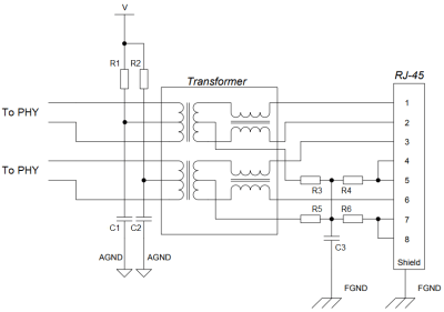
Transformers Make The Data World Turn
One of the Ethernet’s many features is that it’s resilient, and easy to throw around. It’s also galvanically isolated, which means you don’t need a ground connection for a link either – not until you want a shield due to imposed interference, at which point, it might be that you’re pulling cable inside industrial machinery. There are a few tricks to Ethernet, and one such fundamental Ethernet trick is transformers, known as “magnetics” in Ethernet context.
Each pair has to be put through a transformer for the Ethernet port to work properly, as a rule. That’s the black epoxy-covered block you will inevitably see near an Ethernet port in your device. There are two places on the board as far as Ethernet goes – before the transformer, and after the transformer, and they’re treated differently. After the transformer, Ethernet is significantly more resilient to things like ground potential differences, which is how you can wire up two random computers with Ethernet and not even think about things like common mode bias or ground loops, things we must account for in audio, or digital interfaces that haven’t yet gone optical somehow.
If you don’t see the transformer blob next to the Ethernet socket on your board, you might be thinking that your device has skimped on this part somehow, but that’s not the case. If you’re running Ethernet outside of your device, a transformer has to be present, which means that the RJ45 (8P8C) connector is hiding the transformer instead.
A RJ45 jack with integrated magnetics is colloquially referred to as “magjack”, and you’ll have seen one if you’ve ever seen a Raspberry Pi. They might not always be as cheap as individual Ethernet transformers combined with magnetics-less 8P8C sockets, which is why routers, switches and laptop/desktop motherboards rarely ever use them. However, they’re simple to add, and they’re great at saving board space, which is why you will see them on single-board computers and microcontroller boards.
If you need some Ethernet transformers, you can buy them, but on a short notice, harvesting them is more than acceptable. Now, you have to be mindful, of course. One of the parameters of Ethernet transformers is a turns ratio, which can be different depending on the Ethernet chip in use. If you’re using magnetics with a different turns ratio, it might not work, or it might make the chip in question very unhappy; consult the datasheets!
There’s a lot to Ethernet magnetics, including tricks like capacitive coupling, where you can situationally avoid them altogether in very specific situations. We will go through the magnetic intricacies next time, but for now, they bring us to an interesting question. When a microcontroller says that it has an Ethernet port, what does it even imply? Is it enough to add a transformer, or would it need something else? It depends – let’s learn about it!
Two Different Meanings
There are two parts to Ethernet support in terms of hardware. First, there’s the MAC – that’s a block of hardware taking care of the Ethernet protocol logic. You can’t connect it directly to a transformer, but you can connect it to a PHY. The PHY works on the physical layer of Ethernet, it’s the piece of hardware that takes prepared Ethernet packets and translates them onto the wire. Often, MAC and PHY are just two different areas on a single chip, let’s say, in desktop and laptop Ethernet chips, but just as often they’re separate.
If the MAC and PHY are ever separate in your device – say, the MAC is inside your ESP32 chip and the PHY is external, – the MAC will be will be using an interface called MII or GMII or RGMII or something along these lines. It’s a parallel interface, of the kind you want to layout carefully, because it runs fast.
If your chip says that it supports Ethernet, that can mean two things – either it has a MAC and a PHY inside, or it only has a MAC. If the device is you’re playing with is a more networking-oriented chip, say, something like a Carambola or Onion Omega board, you will have the MAC+PHY combo – just wire up a transformer of some kind, even a magjack, and you are ready to go. If you’re looking at a microcontroller with Ethernet support though, say, an ESP32 or some STM, or the Pine64’s Ox64, it’s way more likely to just have a MAC, so you will have to add a compatible PHY to your circuit before you can start wiring up the transformer.
So, Ethernet support for your favorite piece of silicon might mean straightforward wireup, or it might require an extra chip. Thankfully, there’s no shortage of Ethernet-equipped designs to borrow things from – here’s the Olimex ESP32 design for instance, open-source and giving you a circuit known to work in production. Just be careful taking PoE information from Olimex ESP32 boards – their PoE implementation, is, let’s say, situationally useful. Which is why there’s warnings on the page about USB programming, but it’s a great start still!
A Sprinkle Of Resistors
Of course, there are plenty of schematics and reference designs to copy from, and if you do, you might wonder – what are the passives shown inside a magjack schematic, or visible on a board right next to the magnetics? Chances are, you are looking at the Bob Smith termination.
Bob Smith termination on the right of the magnetics, center tap pullups on the left.
Bob Smith termination is something you do for unterminated Ethernet pairs at 10/100Mbps, which you will likely have to work with. It shunts the unused two pairs, both connecting the two wires of each pair together so that the entire pair is treated as a single wire, but also brings the pair to a certain voltage so that any noise induced onto it over the length don’t overlay onto signals on the actually used pairs.
Also, this is one of the things you might burn out if you plug a passive PoE-enabled cable – the resistors will shunt the DC path; which is why PoE-compatible magnetics add extra capacitors in series with each resistor.
On the other side, you will see pullup resistors on the center taps of the active pairs, and capacitors to ground. Omitting either of these will cause your devices to get unhappy, so if your PHY releases magic smoke, or if your Ethernet link glitches out every now and then, you will look back and wish you added them – and it costs nothing to add footprints for them that you can populate later.
Next time, I’d like to show you open-source designs and walk you through a few of them, pointing out things that are there for a reason that you might not be aware of. There are things like isolation perimeters, shield connection, Bob Smith termination values, polarity swaps and PoE tap ways, that you likely want to talk about, and I will highlight appnotes that you’d benefit from reading through, too!
Alan Kirby (left) and Mark Kempf with the LANBridge 100, serial number 0001. (Credit: Alan Kirby)
When Ethernet was originally envisioned, it would use a common, shared medium (the ‘Ether’ part), with transmitting and collision resolution handled by the carrier sense multiple access with collision detection (CSMA/CD) method. While effective and cheap, this limited Ethernet to a 1.5 km cable run and 10 Mb/s transfer rate. As [Alan Kirby] worked at Digital Equipment Corp. (DEC) in the 1980s and 1990s, he saw how competing network technologies including Fiber Distributed Data Interface (FDDI) – that DEC also worked on – threatened to extinguish Ethernet despite these alternatives being more expensive. The solution here would be store-and-forward switching, [Alan] figured.
After teaming up with Mark Kempf, both engineers managed to convince DEC management to give them a chance to develop such a switch for Ethernet, which turned into the LANBridge 100. As a so-called ‘learning bridge’, it operated on Layer 2 of the network stack, learning the MAC addresses of the connected systems and forwarding only those packets that were relevant for the other network. This instantly prevented collisions between thus connected networks, allowed for long (fiber) runs between bridges and would be the beginning of the transformation of Ethernet as a shared medium (like WiFi today) into a star topology network, with each connected system getting its very own Ethernet cable to a dedicated switch port.
A modern normal network card will have onboard an Ethernet controller which, of course, is a pre-programmed microcontroller. Not only does it do the things required to keep a computer on the network, it can even save the primary CPU from having to do certain common tasks required for communicating. But not [Ivan’s]. His homebrew computer — comprised of 7 colorful PCBs — now has an eighth card. You guessed it. That card connects to 10BASE-T Ethernet.
There’s not a microcontroller in sight, although there are RAM chips. Everything else is logic gates, flip flops, and counters. There are a few other function chips, but nothing too large. Does it work? Yes. Is it fast? Um…well, no.
The complete computer.
He can ping others on the network with an 85 ms round trip and serve web pages from his homebrew computer at about 2.6 kB/s. But speed wasn’t the goal here and the end result is quite impressive. He even ported a C compiler to his CPU so he could compile uIP, a networking stack, avoiding the problems of writing his own from scratch.
Some compromises had to be made. The host computer has to do things you normally expect a network card to do. The MTU is 1024 bytes (instead of the more common 1500 bytes, but TCP/IP is made to expect different MTU sizes, which used to be more common when more network interfaces looked like this one).
Even on an FPGA, these days, you are more likely to grab some “IP” to do your Ethernet controller. Rolling your own from general logic is amazing, and — honestly — the design is simpler than we would have guessed. If you check out [Ivan]’s blog, you can find articles on the CPU design, its ALU, and even a VGA video card all from discrete logic. The whole design, including the network card is up on GitHub.
We always can use more tools for FPGA debugging, and the Manta project by [Fischer Moseley] delivers without a shadow of a doubt. Manta lets you add a debug and data transfer channel between your computer and your FPGA, that you can easily access with helpfully included Python libraries.
With just a short configuration file as input, it gives you cores you add into your FPGA design, tapping the signals of interest as an FPGA-embedded logic analyzer, interacting with registers, and even letting you quickly transfer tons of data if you so desire.
Manta is easy to install, is developer-friendly, has been designed in Amaranth, and is fully open source as you would expect. At the moment, Manta supports both UART and Ethernet interfaces for data transfer. As for embedding the Manta cores into your project, they can be exported to both Amaranth and Verilog. You should check out the documentation website — it contains everything you might want to know to get started quick.
The Manta project has started out as our hacker’s MIT thesis, and we’re happy that we can cover it for you all. FPGA-embedded logic analyzers are a fascinating and much-needed tool, and we’ve had our own [Al Williams] tell you about his on-FPGA logic analysis journey!
With so much of our day-to-day networking done wirelessly these days, it can be easy to forget about Ethernet. But it’s a useful standard and can be a great way to add a reliable high-throughput network link to your projects. To that end, [Robert Feranec] and [Stacy Rieck] whipped up a tutorial on how to work with Ethernet on FPGAs.
As [Robert] explains, “many people would like to transfer data from FPGA boards to somewhere else.” That basically sums up why you might be interested in doing this. The duo spend over an hour stepping through doing Ethernet at a very low level, without using pre-existing IP blocks to make it easier. The video explains the basic architecture right down to the physical pins on the device and what they do, all the way up to the logic blocks inside the device that do all the protocol work.
If you just want to get data off an embedded project, you can always pull in some existing libraries to do the job. But if you want to really understand Ethernet, this is a great place to start. There’s no better way to learn than doing it yourself. Files are on GitHub for the curious.
Although Ethernet is generally considered to be a settled matter, its history was anything but peaceful, with its standardization process (under Project 802) leaving its traces to this very day. This is very clear when looking at the different Ethernet frame types in use today, and with many more historical types. While Ethernet II is the most common frame type, 802.2 LLC (Logical Link Control) and 802 SNAP (Subnetwork Access Protocol) are the two major remnants of this struggle that raged throughout the 1980s, even before IEEE Project 802 was created. An in-depth look at this history with all the gory details is covered in this article by [Daniel].
The originally proposed IEEE 802 layout, with the logical link control (LLC) providing an abstraction layer.
We covered the history of Ethernet’s original development by [Robert Metcalfe] and [David Boggs] while they worked at Xerox, leading to its commercial introduction in 1980, and eventual IEEE standardization as 802.3. As [Daniel]’s article makes clear, much of the problem was that it wasn’t just about Ethernet, but also about competing networking technologies, including Token Ring and a host of other technologies, each with its own gaggle of supporting companies backing them.
Over time this condensed into three subcommittees:
802.3: CSMA/CD (Ethernet).
802.4: Token bus.
802.5: Token ring.
An abstraction layer (the LLC, or 802.2) would smooth over the differences for the protocols trying to use the active MAC. Obviously, the group behind the Ethernet and Ethernet II framing push (DIX) wasn’t enamored with this and pushed through Ethernet II framing via alternate means, but with LLC surviving as well, yet its technical limitations caused LLC to mutate into SNAP. These days network engineers and administrators can still enjoy the fallout of this process, but it was far from the only threat to Ethernet.
Ethernet’s transition from a bus to a star topology was enabled by the LANBridge 100 as an early Ethernet switch, allowing it to scale beyond the limits of a shared medium. Advances in copper wiring (and fiber) have further enabled Ethernet to scale from thin- and thicknet coax to today’s range of network cable categories, taking Ethernet truly beyond the limits of token passing, CSMA/CD and kin, even if their legacy will probably always remain with us.
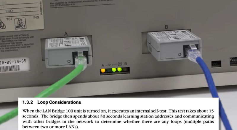
DEC’s LAN Bridge 100 was a major milestone in the history of Ethernet which made it a viable option for the ever-growing LANs of yesteryear and today. Its history is also the topic of a recent video by [The Serial Port], in which [Mark] covers the development history of this device. We previously covered the LANBridge 100 Ethernet bridge and what it meant as Ethernet saw itself forced to scale from a shared medium (ether) to a star topology featuring network bridges and switches.
Featured in the video is also an interview with [John Reed], a field service network technician who worked at DEC from 1980 to 1998. He demonstrates what the world was like with early Ethernet, with thicknet coax (10BASE5) requiring a rather enjoyable way to crimp on connectors. Even with the relatively sluggish 10 Mbit of thicknet Ethernet, adding an Ethernet store and forward bridge in between two of these networks required significant amounts of processing power due to the sheer number of packets, but the beefy Motorola 68k CPU was up to the task.
To prevent issues with loops in the network, the spanning tree algorithm was developed and implemented, forming the foundations of the modern-day Ethernet LANs, as demonstrated by the basic LAN Bridge 100 unit that [Mark] fires up and which works fine in a modern-day LAN after its start-up procedure. Even if today’s Ethernet bridges and switches got smarter and more powerful, it all started with that first LAN Bridge.
For as useful as computers are in the modern ham shack, they also tend to be a strong source of unwanted radio frequency interference. Common wisdom says applying a few ferrite beads to things like Ethernet cables will help, but does that really work?
It surely appears to, for the most part at least, according to experiments done by [Ham Radio DX]. With a particular interest in lowering the noise floor for operations in the 2-meter band, his test setup consisted of a NanoVNA and a simple chunk of wire standing in for the twisted-pair conductors inside an Ethernet cable. The NanoVNA was set to sweep across the entire HF band and up into the VHF; various styles of ferrite were then added to the conductor and the frequency response observed. Simply clamping a single ferrite on the wire helped a little, with marginal improvement seen by adding one or two more ferrites. A much more dramatic improvement was seen by looping the conductor back through the ferrite for an additional turn, with diminishing returns at higher frequencies as more turns were added. The best performance seemed to come from two ferrites with two turns each, which gave 17 dB of suppression across the tested bandwidth.
The question then becomes: How do the ferrites affect Ethernet performance? [Ham Radio DX] tested that too, and it looks like good news there. Using a 30-meter-long Cat 5 cable and testing file transfer speed with iPerf, he found no measurable effect on throughput no matter what ferrites he added to the cable. In fact, some ferrites actually seemed to boost the file transfer speed slightly.
Ferrite beads for RFI suppression are nothing new, of course, but it’s nice to see a real-world test that tells you both how and where to apply them. The fact that you won’t be borking your connection is nice to know, too. Then again, maybe it’s not your Ethernet that’s causing the problem, in which case maybe you’ll need a little help from a thunderstorm to track down the issue.
For someone programming in a high-level language like Python, or even for people who interact primarily with their operating system and the software running on it, it can seem like the computer hardware is largely divorced from the work. Yes, the computer has to be physically present to do something like write a Hackaday article, but most of us will not understand the Assembly language, machine code, or transistor layout well enough to build up to what makes a browser run. [Francis Stokes] is a different breed, though, continually probing these mysterious low-level regions of our computerized world where he was recently able to send an Ethernet packet from scratch.
[Francis] is using an STM32F401 development board for his networking experiments, but even with this powerful microcontroller, Ethernet is much more resource-hungry than we might imagine given its ubiquity in the computing world. Most will turn to a dedicated hardware ASIC to get the Ethernet signals out on the wires rather than bit-banging the protocol, so [Francis] armed himself with a W5100 chip to handle this complex task. Since the W5100 was on a board meant for an Arduino, there were a few kinks to work out, including soldering some wires to the chip, and then there were a few more issues with the signaling, including a bug in the code, which was writing too many times to the same memory, causing the received packet to be enormous while also completely full of garbage.
In the end, [Francis] was able to remove all of the bugs from his code, reliably send an Ethernet packet from his development board, and decode it on a computer. This is an excellent deep dive into the world of signalling and networking from the bottom up. He’s done plenty of these types of investigations before as well, including developing his own AES cryptography from scratch.
Before anyone gets upset, yes we know what [Stargate System] built here isn’t a robot at all; it’s more of a remotely operated vehicle. That doesn’t take away from the fact that this is a very cool build, especially since it has to work in one of the least hospitable and most unpleasant environments possible. The backstory of this project is that the sewer on a 50-year-old house kept backing up, and efforts to clear it only temporarily solved the problem. The cast iron lateral line was reconfigured at some point in its history to include a 120-degree bend, which left a blind spot for the camera used by a sewer inspection service. What’s worse, the bend was close to a joint where a line that once allowed gutters and foundation drains access to the sewer.
To better visualize the problem, [Stargate] turned to his experience building bots to whip up something for the job. The bot had to be able to fit into the pipe and short enough to make the turn, plus it needed to be — erm, waterproof. It also needed to carry a camera and a light, and to be powered and controlled from the other end of the line. Most of the body of the bot, including the hull and the driving gear, was 3D printed from ABS, which allowed the seams to be sealed with acetone later. The drive tracks were only added after the original wheels didn’t perform well in testing. Controlling the gear motors and camera was up to a Raspberry Pi Zero, chosen mostly due to space constraints. An Ethernet shield provided connectivity to the surface over a Cat5 cable, and a homebrew PoE system provided power.
As interesting as the construction details were, the real treat is the down-hole footage. It’s not too graphic, but the blockage is pretty gnarly. We also greatly appreciated the field-expedient chain flail [Stargate] whipped up to bust up the big chunks of yuck and get the pipe back in shape. He did a little bit of robo-spelunking, too, as you do.
We all take Ethernet and its ubiquitous RJ-45 connector for granted these days. But Ethernet didn’t start with twisted pair cable. [Mark] and [Ben] at The Serial Port YouTube channel are taking a deep dive into the twisted history of Ethernet on twisted pair wiring. The earliest forms of Ethernet used RG-8 style coaxial cable. It’s a thick, stiff cable requiring special vampire taps and lots of expensive equipment to operate.
The industry added BNC connectors and RG-58 coax for “cheapernet” or 10Base2. This reduced cost, but still had some issues. Anyone who worked in an office wired with 10Base2 can attest to the network drops whenever a cable was kicked out or a terminator was dropped.
The spark came when [Tim Rock] of AT&T realized that the telephone cables already installed in offices around the world could be used for network traffic. [Tim] and a team of engineers from five different companies pitched their idea to the IEEE 802.3 committee on Feb 14, 1984.
The idea wasn’t popular though — Companies like 3COM, and Digital Equipment Corporation had issues with the network topology and the wiring itself. It took ten years of work and a Herculean effort by IEEE committee chairwoman [Pat Thaler] to create the standard the world eventually came to know as 10Base-T. These days we’re running 10 Gigabit Ethernet over those same connectors.
In the world of (expensive) lab test equipment the GPIB (general purpose interface bus) connection is hard to avoid if you want any kind of automation, but nobody likes wrangling with the bulky cables and compatibility issues when they can just use Ethernet instead. Here [Chris]’s Ethernet-GPIB adapter provides an easy solution, with both Power over Ethernet (PoE) and USB-C power options. Although commercial adapters already exist, these are rather pricey at ~$500.
Features of this adapter include a BOM total of <$50, with power provided either via PoE (802.3af) or USB-C (5V-only). The MCU is an ATmega4809 with the Ethernet side using a Wiznet W5500 SPI Ethernet controller. There is also a serial interface (provided by a CH340X USB-UART adapter), with the firmware based on the AR488 project.
The adapter supports both the VXI-11.2 and Prologix protocols, though not at the same time (due to ROM size limitations). All design documents are available via the GitHub repository, with the author also selling assembled adapters and providing support primarily via the EEVBlog forums.


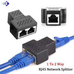
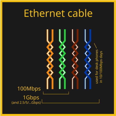 Out of the four pairs, 100 Mbps Ethernet only actually uses two of them, but 1 Gbps Ethernet uses all four. That’s why, on cheap old Ethernet hardware like low-end home routers with 100 Mbps ports, it’s not uncommon to see Ethernet sockets with only four pins out of eight – saving money by all means possible, after all, the two pairs in the cable would not be used anyway. There’s also hack potential in this, for instance, you can


 If you don’t see the transformer blob next to the Ethernet socket on your board, you might be thinking that your device has skimped on this part somehow, but that’s not the case. If you’re running Ethernet outside of your device, a transformer has to be present, which means that the RJ45 (8P8C) connector is hiding the transformer instead.
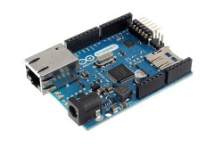 If the MAC and PHY are ever separate in your device – say, the MAC is inside your ESP32 chip and the PHY is external, – the MAC will be will be using an interface called MII or GMII or RGMII or something along these lines. It’s a parallel interface, of the kind you want to layout carefully, because it runs fast.