Wireless connections are cool and all, but sometimes you just need a bit of copper. This interesting article on SV Seeker discusses the various ways of making a tether for a remotely operated vehicle (ROV). They experimented with a number of different cables, including gel-filled Cat 5 designed for burial and wrapping the cable in polypropylene rope to keep it protected and buoyant. They also looked at using a single core solid coax cable with an Ethernet to coax converter on either end wrapped in stretch webbing. The upside of using coax would be the length: it can handle over a mile of cable, which should be more than enough for this project. The downside is that they found that the coax stretches under strain, messing with the signal.
The project seems to be on hiatus at the moment, but there is lots of food for thought here for anyone looking to send data over a long distance. I’m looking to put a webcam in an owl box in my back yard, and I hadn’t come across some of the options they cover here, so I’ll be looking into direct bury rated Cat 5 myself.
When you can get a WiFi-enabled microcontroller for $3, it’s little surprise that many of the projects we see these days have ditched Ethernet. But the days of wired networking are far from over, and there’s still plenty of hardware out there that can benefit from being plugged in. But putting an Ethernet network into your project requires a switch, and that means yet another piece of hardware that needs to get crammed into the build.
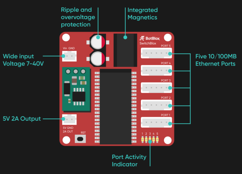
Seeing the need for a small and lightweight Ethernet switch, BotBlox has developed the SwitchBlox. This 45 mm square board has everything you need to build a five device wired network, and nothing you don’t. Gone are the bulky RJ45 jacks and rows of blinkenlights, they won’t do you any good on the inside of a robot’s chassis. But that’s not to say it’s a bare bones experience, either. The diminutive switch features automatic crossover, support for input voltages from 7 V all the way up to 40 V, and management functions accessible over SPI.
If you want to get up and running as quickly as possible, a fully assembled SwitchBlox is available to purchase directly from BotBlox for £149.00. But if you’re not in any particular rush and interested in saving on cost, you can spin up your own version of the Creative Commons licensed board. The C++ management firmware and Python management GUI isn’t ready for prime time just yet, but you’ll be able to build a “dumb” version of the switch with the provided KiCad design files.
The published schematic in their repo uses a Microchip KSZ8895MQXCA as the Ethernet controller, with a Pulse HX1344NL supplying the magnetics for all the ports in a single surface mount package. Interestingly, the two images that BotBlox shows on their product page include different part numbers like H1102FNL and PT61017PEL for the magnetics, and the Pulse H1164NL for the Ethernet controller.
Make Networks Wired Again
There’s no question that WiFi has dramatically changed the way we connect devices. In fact, there’s an excellent chance you’re currently reading these words from a device that doesn’t even have the capability to connect to a wired network. If you’re looking to connect a device to the Internet quickly, it’s tough to beat.
But WiFi certainly isn’t perfect. For one, you have to contend with issues that are inherent to wireless communications such as high latency and susceptibility to interference. There’s also the logistical issues involved in making that initial connection since you need to specify an Access Point and (hopefully) an encryption key. In comparison, Ethernet will give you consistent performance in more or less any environment, and configuration is usually as simple as plugging in the cable and letting DHCP sort the rest out.
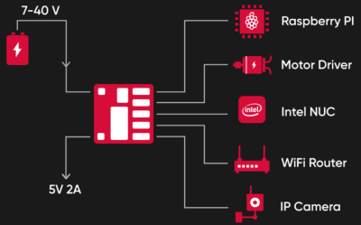
Unfortunately, that whole “plugging in” part can get tricky. Given their size, putting an Ethernet switch into your project to act as an internal bus only works if you’ve got space to burn and weight is of little concern. So as appealing as it might be to build a network into your robot to connect the Raspberry Pi, motor controllers, cameras, etc, it’s rarely been practical.
This little switch could change that, and the fact it’s released under an open source license means hackers and makers will be free to integrate it into their designs. With the addition of an open source management firmware, this device has some truly fascinating potential. When combined with a single board computer or suitably powerful microcontroller, you have the makings of a fully open source home router; something that the privacy and security minded among us have been dreaming of for years.
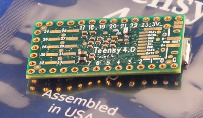
It was only last August that PJRC released Teensy 4.0. At that time, the 4.0 became the fastest microcontroller development board on the planet, a title it still holds as of this writing — or, well, not exactly. Today the Teensy 4.1 has been released, and using the same 600 MHz ARM Cortex M7 under the hood, is now also the fastest microcontroller board. What the 4.1 brings to the table is more peripherals, memory, and GPIOs. While Teensy 4.0 used the same small form factor as the 3.2, Teensy 4.1 uses the larger board size of the 3.5/3.6 to expose the extra goodies.
The now slightly older Teensy 4.0 — released on August 7th of last year — is priced at $19.95, with the new 4.1 version offered at $26.85. It seems that the 4.1 isn’t intended as a replacement for the 4.0, as they serve different segments of the market. If you’re looking for an ultra-fast affordable microcontroller board that lives up to its Teensy name, the 4.0 fits the bill. On the other hand, if you need the additional peripherals broken out and can afford the space of the larger board, the not-as-teensy-sized 4.1 is for you. How big is it? The sample board I measured was 61 x 18 mm (2.4 x 0. 7″), not counting the small protrusion of the micro-usb jack on one end.
Let’s have a look at all the fun stuff PJRC was able to pack into this space.
100 Mbps Ethernet
Add your own jack to enable the 100 Mbps Ethernet port
The big news is that Teensy 4.1 comes with 100 Mbps Ethernet support. To use the Ethernet port, you need to supply external magnetics and an RJ-45 jack. These were left off the board for obvious reasons — even using a jack with integrated magnetics (magjack), it wouldn’t fit on the PCB. Instead, a 6-pin header on the board can connect to an external interface. This also helps keep the price low for those who need the other features of the 4.1 without Ethernet connectivity.
Ethernet and USB host port headers (bottom of PCB)
PJRC will likely sell a DIY kit of the required parts in the future, but they don’t have a release date or pricing yet. For now, you can easily build your own using this OSH Park shared project. The parts list is in the project’s description, with the key part being the magjack, which will set you back around $2.55 in single quantities. Those building a board should note that this is an early version, and it turns out that only the 0.1 uF capacitor is necessary. Paul Stoffregen of PJRC told me that he just received a simpler PCB for testing, and will publish the design once it’s has been thoroughly verified.
The Ethernet port is capable of full 100 Mbps speed and supports the IEEE 1588 precision time protocol, which allows synchronization of clocks to within 100 ns over wired connections, enabling some very interesting possibilities. But, aside from that, just the inclusion of Ethernet on a microcontroller board is a big deal. Before this, you basically had two choices if you needed this kind of connectivity: use a powerful single-board-computer like a Raspberry Pi with all the latency and headaches the required operating system brings for doing low-level or real-time tasks, or add a slow SPI-interfaced Ethernet board to an existing microcontroller. Instead, you can now use the 600 MHz Cortex-M7 on this new board to run high-bandwidth, low-latency embedded applications without fighting an OS.
USB Host Port
Just add a header and cable for USB host functionality
Teensy 4.1 includes a USB host port broken out to a five-pin through-hole header on the inside of the PCB, as was done on the 3.5/3.6 versions. The port will do 480 Mbps high-speed USB. It also adds the power management required for hot-plugging USB peripherals — just add a USB host cable, and you’re good to go. PJRC sells these cables, or you can use a USB2 cable scavenged from an old PC: the pinout is the same. The older Teensy 4.0 only has the USB data lines broken out to surface-mount pads on the PCB.
microSD Card Slot
Like the Teensy 3.6, the new 4.1 board has a microSD card slot on one end to add removable storage. While the pins for this are broken out on the older 4.0 version, the inclusion of this socket greatly simplifies using the interface. And this isn’t like some of the microSD card interfaces you may have seen where you can only use the slower SPI protocol to access the card; here you can use fast, native SDIO.
More Memory!
Teensy 4.1 Bottom Side with user-supplied QSPI RAM chips
Teensy 4.1 has 8 MB of flash memory for program storage, up from the 2 MB on the 4.0 version, quite an enhancement. The microcontroller on the Teensy 4.1– an IMXRT1062, same chip as on the 4.0 — comes with 1 MB of on-chip RAM. It’s easy to think of this as a lot for a microcontroller, at least until you think about the power of this 600 MHz 32-bit processor and what people will want to do with it: audio and graphics applications can easily chew through the 1 MB, as can emulation of other processors/systems, such as for retro gaming. So, the Teensy 4.1 allows addition of either or both of two user-supplied extra memories. On the bottom side of the PCB, there are two SOIC-8 footprints: the one with larger pads will accept a QSPI flash memory, while the smaller footprint is intended for an 8 MB PSRAM (pseudo-static RAM) part. You just solder the part(s) on, and you’re ready to go. Thankfully, they’re both SOIC, which these days is considered by many a joy to hand-solder.
A key feature of these additional memories is that they have a dedicated QSPI bus, which doesn’t slow down the Teensy 4.1’s internal program memory. This is especially important for use with flash memory, due to the long erase and write access, which could otherwise bog down a shared bus. Again, by making these parts optional, and user-supplied, PJRC has reduced the cost of the board for those that don’t need the feature(s); those that need them can bring their own memories.
The 4.1 Breaks Out a Full 16-bit GPIO Port
Teensy 4.0 had surface-mount pads for additional I/O. The Teensy 4.1 moves these to the additional through-hole pads the longer board makes available.
One invariable rule of microcontrollers is that you always need a few more pins. While the processor common to both the Teensy 4.0 and 4.1 has a lot of them, the smaller size of the Teensy 4.0 limited the number of I/O that could be brought out to through-hole headers.
The solution on Teensy 4.0 was to add surface-mount pads for some of the I/O. On Teensy 4.1, the luxurious board real estate allows many more pins to be broken out to headers on the board edge. This brings out an additional serial port, for a total of eight, plus additional analog and digital I/O. The new board also breaks out a full 16 contiguous bits of a GPIO port, which allows for fast, wide parallel I/O. If you’ve ever tried doing this using bits cobbled together from multiple ports, you’ll definitely appreciate not only the convenience, but also the speed this brings to port access.
Wrapping Up
So, what’s the value proposition here over the older Teensy 4.0? If you really want to take full advantage of the hardware available on the IMXRT1062, the 4.1 is the way to go: the larger stock and optional memories, extra pins broken out, Ethernet port, and convenience of the microSD socket and USB host port make this much easier. If you don’t need these extras, or simply need the smaller board size, the Teensy 4.0 is still around, and will save you a few bucks.
[PMercier] clearly loves his old Tektronix TDS3014 scope, which did however lack essentially modern connectivity such as an Ethernet port for control and a USB port for a convenient way to capture screenshots. So he decided to do some in-depth reverse engineering and design his own expansion card for it. The scope already has an expansion port and an expansion card, but given this model was first released in 1998, purchasing an OEM part was not going to be an option.
They don’t make ’em like they used to. Test equipment is today is built to last a decade — but usually lives on much longer. This is certainly true for the previous generations of kit. It’s no surprise that for most of us, hand-me-downs from universities, shrewd eBay purchasing, and even fruitful dumpster dives are a very viable way to attain useful and relevant test equipment. Now, while these acquisitions are more than adequate for the needs of a hobbyist lab, they are admittedly outdated and more to the point, inaccessible from a connectivity and communication standpoint. A modern lab has a very high degree of automated data acquisition and control over ethernet. Capturing screen dumps on a USB is a standard feature. These modern luxuries don’t exist on aging equipment conceived in the age of floppy disks and GPIB.
The first step [PMercier] documents is reverse-engineering the pin-out of the custom expansion connector on the scope. Some pins he notes were easy to deduce, others not so much. This was solved by examining some high-resolution photos of the original expansion card and then using Gimp to do a layered, copper track analysis of the 4 layer PCB! This uncovered most of the unknown pins and the rest required a laborious cross-examination of the scope’s CPU and its BGA package pin-out.
The last piece of the puzzle was to fool the scope into accepting his DIY expansion card. This turned out not to be as simple as pulling a control line. The correct one-hot encoded byte corresponding to the expansion card had to be determined and asserted onto the data bus at the right time.
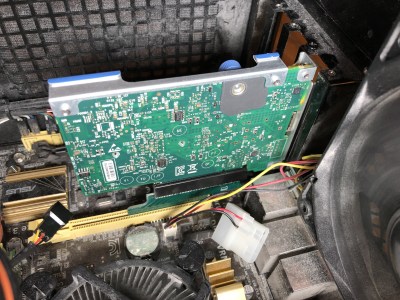
As far as consumer network hardware goes, we’re all expected to be pretty happy with 802.11n WiFi and Gigabit Ethernet over Cat 6 cables. For most home users, that’s plenty of bandwidth for streaming movies and posting K-pop fancams to Twitter on a daily basis. If you want a fatter pipe, things can get expensive, fast. However, [TobleMiner] found a way to use surplus server-grade cards in a regular PC – providing huge bandwidth on a budget.
The adapter is designed to allow a FlexibleLOM card to fit into a regular ATX PCI-E card slot. A small additional bracket should be used to fix the card in place with the typical bracket retention screw.
HPE’s FlexibleLOM standard consists of a special edge connector on HPE servers that lets the end-user fit a variety of network adapters in a form factor designed specifically for blade and rack mount servers. At the electrical level, it’s simply PCI-Express 8x. FlexibleLOM network cards are built for high-speed data center use, often featuring SFP+ and QSFP+ interfaces capable of 10 gigabit and 40 gigabit speeds, respectively.
These cards can be had for under $20 on eBay, but won’t fit in a standard PCI-Express slot. Enter [ToberMiner]’s adapter, which hooks up the relevant PCI-Express lines to where they need to go, and mechanically adapts the FlexibleLOM hardware to fit in a regular ATX PC case.
September 30th, 1980 is the day when Ethernet was first commercially introduced, making it exactly forty years ago this year. It was first defined in a patent filed by Xerox as a 10 Mb/s networking protocol in 1975, introduced to the market in 1980 and subsequently standardized in 1983 by the IEEE as IEEE 802.3. Over the next thirty-seven years, this standard would see numerous updates and revisions.
Included in the present Ethernet standard are not just the different speed grades from the original 10 Mbit/s to today’s maximum 400 Gb/s speeds, but also the countless changes to the core protocol to enable these ever higher data rates, not to mention new applications of Ethernet such as power delivery and backplane routing. The reliability and cost-effectiveness of Ethernet would result in the 1990 10BASE-T Ethernet standard (802.3i-1990) that gradually found itself implemented on desktop PCs.
With Ethernet these days being as present as the presumed luminiferous aether that it was named after, this seems like a good point to look at what made Ethernet so different from other solutions, and what changes it had to undergo to keep up with the demands of an ever-more interconnected world.
The novelty of connecting computers
IBM PCs, connected.
These days, most computers and computerized gadgets are little more than expensive paper weights whenever they find themselves disconnected from the global Internet. Back in the 1980s, people were just beginning to catch up on the things one could do with a so-called ‘local area network’, or LAN. Unlike the 1960s and 1970s era of mainframes and terminal systems, a LAN entailed connecting microcomputers (IBM PCs, workstations, etc.) at for example an office or laboratory.
During this transition from sneakernet to Ethernet, office networks would soon involve thousands of nodes, leading to the wonderful centrally managed office network world. With any document available via the network, the world seemed ready for the paperless office. Although that never happened, the ability to communicate and share files via networks (LAN and WAN) has now become a staple of every day life.
Passing the token
The circuitous world of Token Ring configurations.
What did change was the rapidly changing landscape of commodity network technology. Ethernet’s early competition was a loose collection of smaller network protocols. This includes IBM’s Token Ring. Although many myths formed about the presumed weaknesses of Ethernet in the 1980s, summarized by this document (PDF) from the 1988 SIGCOMM Symposium, ultimately Ethernet turned out to be more than sufficient.
Token Ring’s primary points of presumed superiority were determinism instead of Ethernet’s multiple access with collision detection approach (CSMA/CD). This led to the most persistent myth, that Ethernet couldn’t sustain saturation beyond 37% of its bandwidth.
For cost reasons, the early years of Ethernet was dominated by dumb hubs instead of smarter switches. This meant that the Ethernet adapters had to sort out the collisions. And as anyone who has used Ethernet hubs probably knows, the surest sign of a busy Ethernet network was to glance over at the ‘collision’ LED on the hub(s). As Ethernet switches became more affordable, hubs quickly vanished. Because switches establish routes between two distinct nodes instead of relying on CSMA/CD to sort things out, this prevented the whole collision issue that made hubs (and Ethernet along with it) the target of many jokes, and the myth was busted.
Once Ethernet began to allow for the use of cheaper Cat. 3 (UTP) for 10BASE-T and Cat. 5(e) UTP cables for 100BASE-TX (and related) standards, Ethernet emerged as the dominant networking technology for everything from homes and offices to industrial and automotive applications.
A tree of choices
The increased spectral bandwidth use of copper wiring by subsequent Ethernet standards.
While the list of standards listed under IEEE 802.3 may seem rather intimidating, a more abbreviated list for the average person can be found on Wikipedia as well. Of these, the ones one most likely has encountered at some point are:
10BASE-T (10 Mb, Cat. 3).
100BASE-TX (100 Mb, Cat. 5).
1000BASE-T (1 Gb, Cat. 5).
2.5GBASE-T (2.5 Gb, Cat. 5e).
While the 5GBASE-T and 10GBASE-T standards also have been in use for a few years now, the 25 Gb and 40 Gb versions are definitely reserved for data centers at this point, with the requirement for Cat. 8 cables, and only allowing for runs of up to 36 meters. The remaining standards in the list are primarily aimed at automotive and industrial applications, some of which are fine with 100 Mbit connections.
Still, the time is now slowly arriving where a whole gigabit is no longer enough, as some parts of the world actually have Internet connections that match or exceed this rate. Who knew that at some point a gigabit LAN could become the bottleneck for one’s Internet connection?
ALOHA
The Xerox 9700, the world’s first Ethernet-connected laser printer.
Back in 1972, a handful of engineers over at Xerox’s Palo Alto Research Center (PARC) including Robert “Bob” Metcalfe and David Boggs were assigned the task of creating a LAN technology to provide a way for the Xerox Alto workstation to hook up to the laser printer, which had also been developed at Xerox.
This new network technology would have to allow for hundreds of individual computers to connect simultaneously and feed data to the printer quickly enough. During the design process, Metcalfe used his experience with ALOHAnet, a wireless packet data network developed at the University of Hawaii.
Metcalfe’s first Ethernet sketch.
The primary concept behind ALOHAnet was the use of a shared medium for client transmissions. In order to accomplish this, a protocol was implemented that could be summed up as ‘listen before send’, which would become known as ‘carrier sense multiple access’ (CSMA). This would not only go on to inspire Ethernet, but also WiFi and many other technologies. In the case of Ethernet the aforementioned CSMA/CD formed an integral part of early Ethernet standards.
Coaxial cabling was used for the common medium, which required the use of the cherished terminators at the end of every cable. Adding additional nodes required the use of taps, allowing for the BNC connector on the Ethernet Network Interface Card to be attached to the bus. This first version of Ethernet is also called ‘thicknet’ (10BASE5) due to the rather unwieldy 9.5 mm thick coax cables used. A second version (10BASE2) used much thinner coax cables (RG-58A/U) and was therefore affectionately called ‘thinnet’.
The best plot twist
Don’t forget to terminate your bus.
In the end, it was the use of unshielded, twisted-pair cabling that made Ethernet more attractive than Token Ring. Along with cheaper interface cards, it turned into a no-brainer for people who wanted a LAN at home or the office.
As anyone who has ever installed or managed a 10BASE5 or 10BASE2 network probably knows, interference on the bus, or issues with a tap or AWOL terminator can really ruin a day. Not that figuring out where the token dropped off the Token Ring network is a happy occasion, mind you. Although the common-medium, ‘aether’ part of Ethernet has long been replaced by networks of switches, I’m sure many IT professionals are much happier with the star architecture.
Thus it is that we come from the sunny islands of Hawaii to the technology that powers our home LANs and data centers. Maybe something else would have come along to do what Ethernet does today, but personally I’m quite happy with how things worked out. I remember the first LAN that got put in place at my house during the late 90s as a kid, first to allow my younger brother and I to share files (i.e. LAN gaming), then later to share the cable internet connection. It allowed me to get up to speed with this world of IPX/SPX, TCP/IP and much more network-related stuff, in addition to the joys of LAN parties and being the system administrator for the entire family.
Happy birthday, Ethernet. Here is to another forty innovative, revolutionary years.
The Gigablox takes its mission seriously, with its compact size the ultimate design goal. The entire switch fits on a tiny 45 mm x 45 mm PCB. To this end, it eschews the common RJ45 connector, which is bulkier than necessary. Instead, thin Molex PicoBlade connectors are used for the five ports on board. Cables are included to convert between the two connectors, and obviously crimping ones own is easy to do, too. For those who need to connect more devices, several Gigablox can be hooked up in the same way as any other Ethernet switch. The Gigablox is a non-blocking switch, too – meaning all five ports can run at full speed simultaneously.
The design is the sequel to the SwitchBlox, and the later SwitchBlox Nano, both designed by [Josh Elijah] earlier this year. The pace of development is impressive, and it’s great to see [Josh] bring Gigabit speeds to the compact form factor. We can imagine a few good uses for these boards; share your best ideas in the comments below! Video after the break.
Airgapping refers to running a machine or machines without connections to external networks. Literally, a gap of air exists between the machine and the outside world. These measures present a challenge to those wishing to exfiltrate data from such a machine, leading to some creative hacks. [Jacek] has recently been experimenting with leaking data via Ethernet adapters.
The hack builds on [Jacek]’s earlier work with the Raspberry Pi 4, in which the onboard adapter is rapidly switched between 10 and 100 Megabit modes to create a signal that can be picked up via radio up to 100 meters away. Since then, [Jacek] determined the Raspberry Pi 4, or at least his particular one, seems to be very leaky of RF energy from the Ethernet port. He decided to delve deeper by trying the same hack out on other hardware.
Using a pair of Dell laptops connected back to back with an Ethernet cable, the same speed-switching trick was employed. However, most hardware takes longer to switch speeds than the Pi 4; usually on the order of 2-5 seconds. This limited the signalling speed, but [Jacek] was able to set this up to exfiltrate data using QRSS, also known as very slow speed Morse code. The best result was picking up a signal from 10 meters away, although [Jacek] suspects this could be improved with better antenna hardware.
A common sight on factory floors, stack lights are used to indicate the status of machinery to anyone within visual range. But hackers have found out you can pick them up fairly cheap online, so we’ve started to see them used as indicators in slightly more mundane situations than they were originally intended for. [Tyler Ward] recently decided he wanted his build own network controlled stack light, and thought it would double as a great opportunity to dive into the world of Power Over Ethernet (PoE).
Now the easy way to do this would be to take the Raspberry Pi, attach the official PoE Hat to it, and toss it into a nice enclosure. Write some code that toggles the GPIO pins attached to the LEDs in the stack light, and call it a day. Would be done in an afternoon and you could be showing it off on Reddit by dinner time. But that’s not exactly what [Tyler] had in mind.
On the software side [Tyler] has developed a firmware for the ESP32 that supports both Art-Net and RDM protocols, which are subsets of the larger DMX protocol. That means the controller should be compatible with existing software designed for controlling theatrical lighting systems. If you’d rather take a more direct approach, the firmware also sports a web interface and simple HTTP API to provide some additional flexibility.
When people like Bell and Marconi invented telephones and radios, you have to wonder who they talked to for testing. After all, they had the first device. [Jeff] had a similar problem. He got a 10 gigabit network card working with the Raspberry Pi Compute Module. But he didn’t have any other fast devices to talk to. Simple, right? Just get a router and another network card. [Jeff] thought so too, but as you can see in the video below, it wasn’t quite that easy.
Granted, some — but not all — of the hold-ups were self-inflicted. For example, doing some metalwork to get some gear put in a 19-inch rack. However, some of the problems were unavoidable, such as the router that has 10 Gbps ports, but not enough throughput to actually move traffic at that speed. Recabling was also a big task.
A lot of the work revolved around side issues such as fan noises and adding StarLink to the network that didn’t really contribute to the speed, but we understand distractions in a project.
The router wasn’t the only piece of gear that can’t handle the whole 10 Gbps data stream. The Pi itself has a single 4 Gbps PCI lane, so the most you could possibly get would be 4 Gbps and testing showed that the real limit is not quite 3.6 Gbps. That’s still impressive and the network card offloading helped the PI’s performance, as well.
On a side note, if you ever try to make videos yourself, watching the outtakes at the end of the video will probably make you feel better about your efforts. We all must have the same problems.
Hopefully by now most of us know better than to rent a modem from an internet service provider. Buying your own and using it is almost always an easy way to save some money, but even then these pieces of equipment won’t last forever. If you’re sitting on an older cable modem and thinking about tossing it in the garbage, there might be a way to repurpose it before it goes to the great workbench in the sky. [kc9umr] has a way of turning these devices into capable spectrum analyzers.
The spectrum analyzer feature is a crucial component of cable modems to help take advantage of the wide piece of spectrum that is available to them on the cable lines. With some of them it’s possible to access this feature directly by pointing a browser at it, but apparently some of them have a patch from the cable companies to limit access. By finding one that hasn’t had this patch applied it’s possible to access the spectrum analyzer, and once [kc9umr] attached some adapters and an antenna to his cable modem he was able to demonstrate it to great effect.
While it’s somewhat down to luck as to whether or not any given modem will grant access to this feature, for the ones that do it seems like a powerful and cheap tool. It’s agnostic to platform, so any computer on the network can access it easily, and compared to an RTL-SDR it has a wider range. There are some limitations, but for the price it can’t be beat which will cost under $50 in parts unless you happen to need two inputs like this analyzer .
Good news, everyone! Security researcher [Mordechai Guri] has given us yet another reason to look askance at our computers and wonder who might be sniffing in our private doings.
This time, your suspicious gaze will settle on the lowly Ethernet cable, which he has used to exfiltrate data across an air gap. The exploit requires almost nothing in the way of fancy hardware — he used both an RTL-SDR dongle and a HackRF to receive the exfiltrated data, and didn’t exactly splurge on the receiving antenna, which was just a random chunk of wire. The attack, dubbed “LANtenna”, does require some software running on the target machine, which modulates the desired data and transmits it over the Ethernet cable using one of two methods: by toggling the speed of the network connection, or by sending raw UDP packets. Either way, an RF signal is radiated by the Ethernet cable, which was easily received and decoded over a distance of at least two meters. The bit rate is low — only a few bits per second — but that may be all a malicious actor needs to achieve their goal.
To be sure, this exploit is quite contrived, and fairly optimized for demonstration purposes. But it’s a pretty effective demonstration, but along with the previously demonstrated hard drive activity lights, power supply fans, and even networked security cameras, it adds another seemingly innocuous element to the list of potential vectors for side-channel attacks.
When Tonga’s Hunga-Tonga Hunga-Ha’apai volcano erupted on January 15, one hacker in the UK knew just what to do. Sandy Macdonald from York quickly cobbled together a Raspberry Pi and a pressure/humidity sensor board and added a little code to create a recording barometer. The idea was to see if the shock wave from the eruption would be detectable over 16,000 km away — and surprise, surprise, it was! It took more than 14 hours to reach Sandy’s impromptu recording station, but the data clearly show a rapid pulse of increasing pressure as the shockwave approached, and a decreased pressure as it passed. What’s more, the shock wave that traveled the “other way” around the planet was detectable too, about seven hours after the first event. In fact, data gathered through the 19th clearly show three full passes of the shockwaves. We just find this fascinating, and applaud Sandy for the presence of mind to throw this together when news of the eruption came out.
Good news for professional astronomers and others with eyes turned skyward — it seems like the ever-expanding Starlink satellite constellation isn’t going to kill ground-based observation. At least that’s the conclusion of a team using the Zwicky Transient Facility (ZTF) at the Palomar Observatory outside San Diego. ZTF is designed to catalog anything that blinks, flashes, or explodes in the night sky, making it perfect to detect the streaks from the 1,800-odd Starlink satellites currently in orbit. They analyzed the number of satellite transients captured in ZTF images, and found that fully 20 percent of images show streaks now, as opposed to 0.5 percent back in 2019 when the constellation was much smaller. They conclude that at the 10,000 satellite full build-out, essentially every ZTF image will have a streak in it, but since the artifacts are tiny and well-characterized, they really won’t hinder the science to any appreciable degree.
Speaking of space, we finally have a bit of insight into the causes of space anemia. The 10% to 12% decrease in red blood cells in astronauts during their first ten days in space has been well known since the dawn of the Space Age, but the causes had never really been clear. It was assumed that the anemia was a result of the shifting of fluids in microgravity, but nobody really knew for sure until doing a six-month study on fourteen ISS astronauts. They used exhaled carbon monoxide as a proxy for the destruction of red blood cells (RBCs) — one molecule of CO is liberated for each hemoglobin molecule that’s destroyed — and found that the destruction of RBCs is a primary effect of being in space. Luckily, there appears to be a limit to how many RBCs are lost in space, so the astronauts didn’t suffer from complications of severe anemia while in space. Once they came back to gravity, the anemia reversed, albeit slowly and with up to a year of measurable changes to their blood.
And finally, if you’re in the mood for a contest, why not check out WIZNet’s Ethernet HAT contest? The idea is to explore what a Raspberry Pi Pico with Ethernet attached is good for. WIZNet has two flavors of board: one is an Ethernet HAT for the Pico, while the other is as RP2040 with built-in Ethernet. The good news is, if you submit an idea, they’ll send you a board for free. We love it when someone from the Hackaday community wins a contest, so if you enter, be sure to let us know. And hurry — submissions close January 31.
If you’ve had any dealings with Cat 5 and Cat 6 cable, and let’s be honest, who hasn’t, you’ve probably wrestled with lengths anywhere from 1 meter to 25 meters if you’re hooking up a long haul. Network admins will be familiar with the 0.1 m variety for neat hookups in server cabinets. However, a Reddit community has recently taken things further.
It all started on r/ubiquiti, where user [aayo-gorkhali] posted a custom-built cable just over 2 inches long. The intention was to allow a Ubiquiti U6-IW access point to be placed on a wall. The tiny cable was used to hook up to the keystone jack that formerly lived in that position, as an alternative to re-terminating the wall jack into a regular RJ45 connector.
Naturally this led to an arms race, with [darkw1sh] posting a shorter example with two RJ-45 connectors mounted back to back with the bare minimum of cable crimped into the housings. [Josh_Your_IT_Guy] went out the belt sander to one-up that effort, measuring just over an inch in length.
[rickyh7] took things further, posting a “cable” just a half-inch long (~13 mm). In reality, it consists of just the pinned section of two RJ-45 connectors mounted back to back, wired together in the normal way. While electrically it should work, and it passes a cable tester check, it would be virtually impossible to actually plug it into two devices at once due to its tiny length.
We want to see this go to the logical end point, though. This would naturally involve hacking away the plastic casings off a pair of laptops and soldering their motherboards together at the traces leading to the Ethernet jack. Then your “cable” is merely the width of the solder joint itself.
Alternatively, you could spend your afternoon learning about other nifty hacks with Ethernet cables that have more real-world applications!
Ethernet cable testers are dime a dozen, but none of them are as elegant and multimeter-friendly as this tester from our Hackaday.io regular, [Bharbour]. An Ethernet cable has 8 wires, and the 9 volts of easily available batteries come awfully close to that – which is why the board has a voltage divider! On the ‘sender’ end, you just plug this board onto the connector, powered by a 9 volt battery. On the “receiver” end, you take your multimeter out and measure the testpoints – TP1 should be at one volt, TP2 at two volts, and so on.
As a result, you can easily check any of the individual wires, as opposed to many testers which only test pair-by-pair. This also helps you detect crossover and miswired cables – while firmly keeping you in the realm of real-life pin numbers! This tester is well thought-out when it comes to being easily reproducible – the PCB files are available in the “Files” section, and since the “receiver” and “sender” PCBs are identical, you only need to do a single “three PCBs” order from OSHPark in order to build your own!
When it comes to impromptu enclosures, [Paul Wallace] is a man after our own hearts, for his serial-to-Ethernet converters allowing him to control older test equipment were housed in takeaway curry containers. Once the test equipment pile had grown it became obvious that a pile of curry containers was a bit unwieldy, even if the curry had been enjoyable, so he set about creating an all-in-one multiway serial to Ethernet box.
Reminiscent of the serial terminal access controllers that were found in dumb terminal sites back in the day, it’s a box with eight DB-9 connectors for serial ports and a single RJ45 Ethernet port. Inside is a Teensy 4.1 which packs a PHY and eight hardware serial ports, and a pile of MAX232 level converter modules. These have a small modification to wire in the CTS and RTS lines, and the whole is clothed in a custom 3D printed case.
The result is a very neat, almost commercial standard box that should save him quite a bit of space. Not everyone has eight devices to drive, so if you have just one how about using an ESP8266?
Whilst the Raspberry Pi RP2040 is quite a capable little chip, on the whole it’s nothing really special compared to the big brand offerings. But, the PIO peripheral is a bit special, and its inclusion was clearly a masterstroke of foresight, because it has bestowed the platform all kinds of capabilities that would be really hard to do any other way, especially for the price.
Our focus this time is on Ethernet, utilizing the PIO as a simple serialiser to push out a pre-formatted bitstream. [kingyo] so far has managed to implement the Pico-10BASE-T providing the bare minimum of UDP transmission (GitHub project) using only a handful of resistors as a proof of concept. For a safer implementation it is more usual to couple such a thing magnetically, and [kingyo] does show construction of a rudimentary pulse transformer, although off the shelf parts are obviously available for this. For the sake of completeness, it is also possible to capacitively couple Ethernet hardware (checkout this Micrel app note for starters) but it isn’t done all that much in practice.
Inside the expedient pulse transformer.
UDP is a simple Ethernet protocol for transferring application data. Being connection-less, payload data are simply formatted into a packet buffer up front. This is all fine, until you realize that the packets are pretty long and the bitrate can be quite high for a low-cost uC, which is why devices with dedicated Ethernet MAC functionality have a specific hardware serialiser-deserialiser (SERDES) block just for this function.
Like many small uC devices, the RP2040 does not have a MAC function built in, but it does have the PIO, and that can easily be programmed to perform the SERDES function in only a handful of lines of code, albeit only currently operating at 10 MBit/sec. This will cause some connectivity problems for modern switch hardware, as they will likely no longer support this low speed, but that’s easily solved by snagging some older switch hardware off eBay.
As for the UDP receive, that is promised for the future, but for getting data out of a remote device over a wired network, Pico-10BASE-T is a pretty good starting point. We’ve seen a few projects before that utilize the PIO to generate high speed signals, such as DVI, albeit with a heavy dose of overclocking needed. If you want a bit more of an intro to all things Pico, you could do worse than check out this video series we highlighted a while back.
A few days ago we covered a project that brought Ethernet connectivity to the Raspberry Pi Pico using little more than some twisted pair and a RJ-45 connector. It was a neat trick, but not exactly ready for widespread adoption. Looking to improve on things a bit, [tvlad1234] has taken that project’s code and rewritten it into a friendly library you can use with any RP2040 board.
In case you missed it, the initial demo did 10BASE-T transmission by bit-banging with the PIO, and was able to send UDP messages to devices on the wired LAN. It was an impressive accomplishment, but its code didn’t make it easy to build your project around it. This new library makes UDP messaging as easy as a printf, offloading all non-PIO-managed Ethernet signal work onto the RP2040’s second CPU core. The library even generates a random MAC address out of your flash chip’s serial number!
As a demonstration of the new library, [tvlad1234] has put together a simple Ethernet-connected temperature monitor using the BMP085 or BMP180 sensor connect over I2C. If you feel like you could use an Ethernet transmit-only sensor in your life, browsing the source code would be a great start.
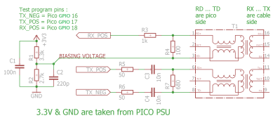
These days, even really cheap microcontroller boards have options that will give you Ethernet or WiFi access. But what if you have a Raspberry Pi Pico board and you really want to MacGyver yourself a network connection? You could do worse than check out this project by [holysnippet] that gives you a bit-banged bidirectional Ethernet port using only scrap passive components and software.
This project is similar to one we shared back in August by [kingyo], but differs in that what [holysnippet] has achieved is a fully-functional (albeit only around 7 Mbps) Ethernet port, rather than a simple UDP transmit device. The Ethernet connection itself is handled by the lwip stack. Connection to the RJ45 socket can be made from any of the Pi Pico pins, provided TX_NEG is followed directly by TX_POS, but the really hacky part is in the hardware.
Schematic showing the empirically-determined passive component values required.
Rather than developing hardware that would protect the Pico, this design admits that it “shamefully relies on the Pico’s input protection devices” to limit the Ethernet voltages to 3.3 V.
You’ll need an isolation transformer from some old Ethernet-enabled gear (either standalone or as part of a magnetic jack), but then it’s only resistors and capacitors from there. There are warnings not to connect this to PoE networks for obvious reasons, and the component layout needs to keep in mind the ~20 MHz frequencies involved, but to get this working at all feels like quite a feat.
Normally, there’d be no reason to go to these lengths, but it’s always educational to see if it can be done and, with the current component shortages, this is another trick to keep up your sleeve for emergencies!
Putting ports where they shouldn’t belong is not a new idea, of course. Back in the day we even shared an inadvisable ATTINY implementation of bit-banged Ethernet with no protection at all.
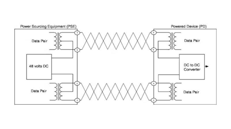
Most readers will be familiar with Ethernet networks in some form, in particular the Cat5 cables which may snake around the back of our benches. In a similar vein, we’ll have used power over Ethernet, or PoE, to power devices such as webcams. Buy a PoE router or switch, plug in a cable, and away you go! But what lies behind PoE, and how does it work? [Alan] has written a comprehensive guide, based on experience working with the technology.
What we get first is a run-down of the various topographies involved. Then [Alan] dives into the way a PoE port polls for a PoE device to be connected, identifies it, and ramps up the voltage. Explaining the various different circuits is particularly valuable. The final part of the show deals with the design of a PoE module, with a small switching power supply to give the required 48 volts.
All in all, this should be required reading for anyone who works with Ethernet, because it’s one of those things too often presented as something of a black box. If you’re thirsty for more, it’s a subject Hackaday have touched on too in the past.